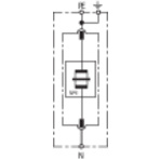
DEHNgap

N-PE Lightning Current Arrester

For protecting low-voltage consumer’s installations against surges and even direct lightning strikes. For installation in conformity with the lightning protection zone concept at the boundaries from 0A– 1 ("3+1" circuit).
  • Discharge capacity up to 100 kA (10/350 µs)
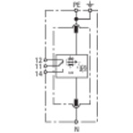
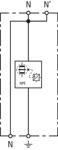
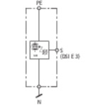
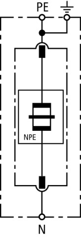
  • Total current arrester specifically designed for installation in 3+1 and 1+1 configurations of TT systems according to IEC 60364-5-53 between neutral conductor N and protective conductor PE
  • Creepage discharge spark gap technology
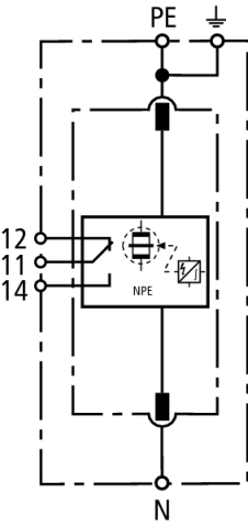
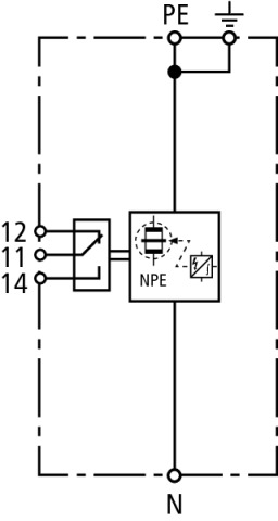
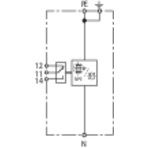
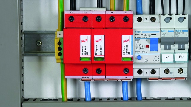
  • Operating state / fault indication by green / red indicator flag in the inspection window

Version

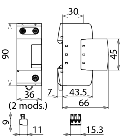
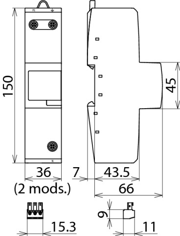
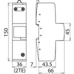
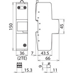
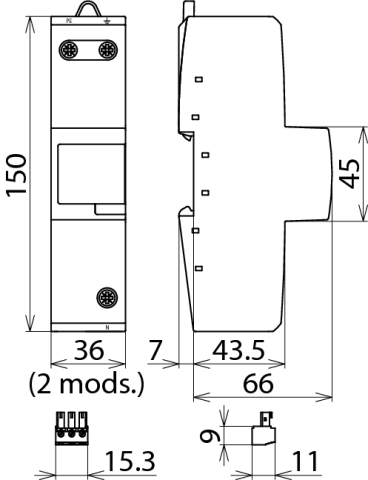
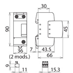
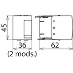
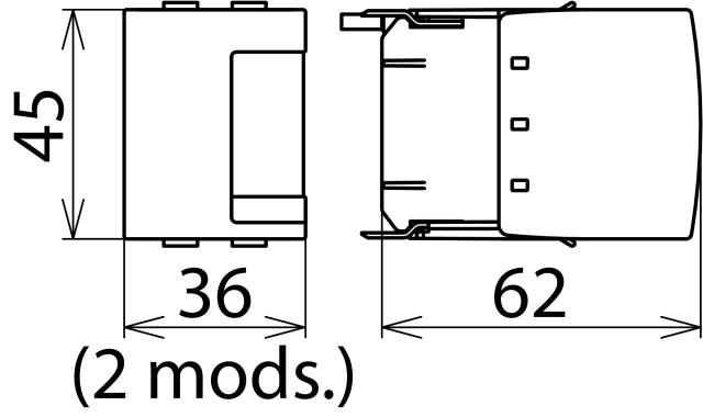
DEHNgap M 255 (FM): Coordinated and modular single-pole N-PE lightning current arrester
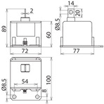
DEHNgap Maxi 1 255 S: Coordinated single-pole N-PE lightning current arrester for busbars
DEHNgap Maxi 1 255 (FM): Coordinated single-pole N-PE lightning current arrester for 3+1 configurations with DEHNvenCI
DEHNgap Maxi 440 (FM): Coordinated single-pole N-PE lightning current arrester for UC = 440 V a.c.
DEHNgap H M 255: Modular single-pole N-PE lightning current arrester

Details

Being total current arresters between the neutral and protective conductor in TT systems, the single-pole N-PE lightning current arresters of type DEHNgap M, DEHNgap Maxi, DEHNgap Maxi S and DEHNgap H M help to ensure fulfilling the requirements for protecting personnel and equipment in "1+1" or "3+1" circuits. The creepage discharge spark gaps were specifically developed to meet this challenge. With a discharge capacity up to 100 kA (10/350 µs), they fulfil the highest national and international lightning protection standards. Their leakage-current-free spark gap design allows the devices to be used in areas upstream of the meter panel according to the German VDN guideline.
The DEHNgap M, DEHNgap Maxi S and DEHNgap Maxi coordinated N-PE lightning current arresters hold a special position among total current arresters. Due to their low voltage protection level, they can be directly coordinated with N-PE surge arresters of the DEHNguard M family and DEHNgap C S surge arresters without additional decoupling coil. If lightning current arresters are to be installed along with surge arresters at the same location, no additional DEHNgap C S is required thanks to the low voltage protection level of DEHNgap M and DEHNgap Maxi.
The design and installation of DEHNgap Maxi S arresters are adapted to the unique nature of low-voltage switchgear installations and entirely complement the use of DEHNbloc Maxi S arresters.
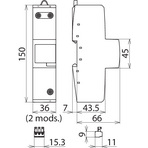
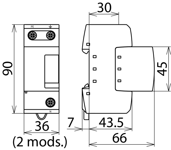
The multifunctional terminals of the DIN rail mounted DEHNgap M and DEHNgap H M devices are suitable for connecting conductors and busbars, allowing comfortable wiring with other DIN rail mounted terminals. With its functional Red/Line design, DEHNgap M combines safety and ease of use in a single device. The mechanical operating state / fault indication as well as the unique module locking system stand for fulfilling high safety requirements. The module locking system fixes the protection modules to the base part. Neither vibration during transport nor the enormous electromagnetic forces of discharge can loosen the protection modules. Nevertheless, they can be easily replaced without tools by simply pressing the easy-to-use module release button of the protection module. Each protection module is mechanically coded to ensure against installing an incorrect module. Apart from the standard visual indication of DEHNgap M, DEHNgap M ... FM features a three-pole remote signalling terminal. With its floating changeover contact, the remote signal can be used as a break or make contact according to the particular circuit concept.

Models

DEHNgap M 255 (FM)

DEHNgap Maxi 1 255 S

DEHNgap Maxi 1 255 (FM)

DEHNgap Maxi 440 (FM)

DEHNgap H M 255

DEHNgap M 255 (FM)

Basic circuit diagram DGP M 255 FMDimension drawing DGP M 255 FM

Coordinated and modular single-pole N-PE lightning current arrester; FM version with floating remote signalling contact.


Specifications

Type
Part No.
SPD according to EN 61643-11 / IEC 61643-11
Max. continuous operating voltage (a.c.) (UC)
Lightning impulse current (10/350 µs) (Iimp)
Specific energy (W/R)
Voltage protection level (UP)
Follow current extinguishing capability (a.c.) (Ifi)
Response time (tA)
Temporary overvoltage (TOV) (UT) – Characteristic
Operating temperature range (parallel connection) (TUP)
Operating temperature range (series connection) (TUS)
Operating state / fault indication
Number of ports
Cross-sectional area (N, PE, 9) (min.)
Cross-sectional area (N, PE) (max.)
Cross-sectional area (9) (max.)
For mounting on
Enclosure material
Place of installation
Degree of protection
Capacity
Approvals
Type of remote signalling contact
Switching capacity (a.c.)
Switching capacity (d.c.)
Cross-sectional area for remote signalling terminals
Weight
GTIN
PU
Part No.
  • DGP M 255
  • 961 101
  • type 1 / class I
  • 255 V (50 / 60 Hz)
  • 100 kA
  • 2.50 MJ/ohms
  • ≤ 1.5 kV
  • 100 Arms
  • ≤ 100 ns
  • 1200 V / 200 ms – withstand
  • -40 °C ... +80 °C
  • -40 °C ... +60 °C
  • green / red
  • 1
  • 10 mm2 solid / flexible
  • 50 mm2 stranded / 35 mm2 flexible
  • 35 mm2 stranded / 25 mm2 flexible
  • 35 mm DIN rails acc. to EN 60715
  • thermoplastic, red, UL 94 V-0
  • indoor installation
  • IP 20
  • 2 module(s), DIN 43880
  • VDE, KEMA, UL
  •  
  •  
  •  
  •  
  • 315 g
  • 4013364118676
  • 1 pc(s)
  • 961 101
  • Specifications (PDF)
  • More
  • DGP M 255 FM
  • 961 105
  • type 1 / class I
  • 255 V (50 / 60 Hz)
  • 100 kA
  • 2.50 MJ/ohms
  • ≤ 1.5 kV
  • 100 Arms
  • ≤ 100 ns
  • 1200 V / 200 ms – withstand
  • -40 °C ... +80 °C
  • -40 °C ... +60 °C
  • green / red
  • 1
  • 10 mm2 solid / flexible
  • 50 mm2 stranded / 35 mm2 flexible
  • 35 mm2 stranded / 25 mm2 flexible
  • 35 mm DIN rails acc. to EN 60715
  • thermoplastic, red, UL 94 V-0
  • indoor installation
  • IP 20
  • 2 module(s), DIN 43880
  • VDE, KEMA, UL
  • changeover contact
  • 250 V / 0.5 A
  • 250 V / 0.1 A; 125 V / 0.2 A; 75 V / 0.5 A
  • max. 1.5 mm2 solid / flexible
  • 320 g
  • 4013364118683
  • 1 pc(s)
  • 961 105
  • Specifications (PDF)
  • More

DEHNgap Maxi 1 255 S

Basic circuit diagram DGPM 1 255 SDimension drawing DGPM 1 255 S

Coordinated single-pole N-PE lightning current arrester for busbars.


Specifications

Type
Part No.
SPD according to EN 61643-11 / IEC 61643-11
Max. continuous operating voltage (a.c.) (UC)
Lightning impulse current (10/350 µs) (Iimp)
Specific energy (W/R)
Voltage protection level (UP)
Follow current extinguishing capability (a.c.) (Ifi)
Response time (tA)
Temporary overvoltage (TOV) (UT) – Characteristic
Operating temperature range (TU)
Number of ports
For mounting on
Connection
Operating state monitoring
Connection for DSI E 3 (S) (min.)
Connection for DSI E 3 (S) (max.)
Enclosure material
Place of installation
Dimensions (W x H x D)
Weight
GTIN
PU
Part No.
  • DGPM 1 255 S
  • 900 050
  • type 1 / class I
  • 255 V (50 / 60 Hz)
  • 100 kA
  • 2.50 MJ/ohms
  • ≤ 2.5 kV (80 cm connecting cable included)
  • 100 Arms
  • ≤ 100 ns
  • 1200 V / 200 ms – withstand
  • -40 °C ... +80 °C
  • 1
  • N busbars, min. 35 mm2
  • via cable lug, min. 35 mm² / max. 50 mm2
  • via DEHNsignal DSI E 3
  • 1 mm2 solid / flexible
  • 2.5 mm2 solid / flexible
  • thermoplastic, red, UL 94 V-0
  • indoor installation
  • 72 x 89 x 100 mm
  • 507 g
  • 4013364107496
  • 1 pc(s)
  • 900 050
  • Specifications (PDF)
  • More
    • Further Pictures
      Basic circuit diagram DGPM 1 255 S
      open PDF
      Dimension drawing DGPM 1 255 S
      open PDF
      Further Information
      Product Specifications (Text)

      Back

      DEHNgap Maxi 1 255 S N-PE lightning current arrester
      Coordinated single-pole N-PE lightning current arrester 
      for industrial busbar systems
      Type 1 SPD according to EN 61643-11
      Pressurised encapsulated creeping discharge spark gap 
      Max. continuous operating voltage: 255 V a.c.
      Voltage protection level:	<= 2.5 kV (including 80 cm connecting cable)
      Lightning impulse current (10/350): 100 kA
      Follow current extinguishing capability: 100 kArms
      TOV resistance: 1200 V/200 ms
      Energy-coordinated with arresters of the Red/Line series 
      according to IEC 62305-4 
      Installation on N busbars min. 35 mm2 
      Dimensions (W x H x D): (72 x 89 x 100) mm

      delivery and installation.

      Brand: DEHN
      Type: DGPM 1 255 S
      Part No.: 900 050

      or equivalent.
      Installation Instructions
      Certificates
      CE_DGPM_1_255_S
      CAD-Data for registered Users
      900050.stp
      900050.igs
      900050.jt
      900050.dwg
      900050m_D.dxf

DEHNgap Maxi 1 255 (FM)

Basic circuit diagram DGPM 1 255 FMDimension drawing DGPM 1 255 FM

Coordinated single-pole N-PE lightning current arrester; FM version with floating remote signalling contact.


Specifications

Type
Part No.
SPD according to EN 61643-11 / IEC 61643-11
Max. continuous operating voltage (a.c.) (UC)
Lightning impulse current (10/350 µs) (Iimp)
Specific energy (W/R)
Voltage protection level (UP)
Follow current extinguishing capability (a.c.) (Ifi)
Response time (tA)
Temporary overvoltage (TOV) (UT) – Characteristic
Operating temperature range (parallel connection) (TUP)
Operating temperature range (series connection) (TUS)
Operating state / fault indication
Number of ports
Cross-sectional area (N, PE, 9) (min.)
Cross-sectional area (N, PE) (max.)
Cross-sectional area (9) (max.)
For mounting on
Enclosure material
Place of installation
Degree of protection
Capacity
Type of remote signalling contact
Switching capacity (a.c.)
Switching capacity (d.c.)
Cross-sectional area for remote signalling terminals
Weight
GTIN
PU
Part No.
  • DGPM 1 255
  • 961 180
  • type 1 / class I
  • 255 V (50 / 60 Hz)
  • 100 kA
  • 2.50 MJ/ohms
  • ≤ 1.5 kV
  • 100 Arms
  • ≤ 100 ns
  • 1200 V / 200 ms – withstand
  • -40 °C ... +80 °C
  • -40 °C ... +60 °C
  • green / red
  • 1
  • 10 mm2 solid / flexible
  • 50 mm2 stranded / 35 mm2 flexible
  • 35 mm2 stranded / 25 mm2 flexible
  • 35 mm DIN rails acc. to EN 60715
  • thermoplastic, red, UL 94 V-0
  • indoor installation
  • IP 20
  • 2 module(s), DIN 43880
  •  
  •  
  •  
  •  
  • 370 g
  • 4013364157323
  • 1 pc(s)
  • 961 180
  • Specifications (PDF)
  • More
  • DGPM 1 255 FM
  • 961 185
  • type 1 / class I
  • 255 V (50 / 60 Hz)
  • 100 kA
  • 2.50 MJ/ohms
  • ≤ 1.5 kV
  • 100 Arms
  • ≤ 100 ns
  • 1200 V / 200 ms – withstand
  • -40 °C ... +80 °C
  • -40 °C ... +60 °C
  • green / red
  • 1
  • 10 mm2 solid / flexible
  • 50 mm2 stranded / 35 mm2 flexible
  • 35 mm2 stranded / 25 mm2 flexible
  • 35 mm DIN rails acc. to EN 60715
  • thermoplastic, red, UL 94 V-0
  • indoor installation
  • IP 20
  • 2 module(s), DIN 43880
  • changeover contact
  • 250 V / 0.5 A
  • 250 V / 0.1 A; 125 V / 0.2 A; 75 V / 0.5 A
  • max. 1.5 mm2 solid / flexible
  • 370 g
  • 4013364157330
  • 1 pc(s)
  • 961 185
  • Specifications (PDF)
  • More

DEHNgap Maxi 440 (FM)

Basic circuit diagram DGPM 440 FMDimension drawing DGPM 440

Coordinated single-pole N-PE lightning current arrester; FM version with floating remote signalling contact.


Specifications

Type
Part No.
SPD according to EN 61643-11 / IEC 61643-11
Max. continuous operating voltage (a.c.) (UC)
Lightning impulse current (10/350 µs) (Iimp)
Specific energy (W/R)
Voltage protection level (UP)
Follow current extinguishing capability (a.c.) (Ifi)
Response time (tA)
Temporary overvoltage (TOV) (UT) – Characteristic
Operating temperature range (parallel connection) (TUP)
Operating temperature range (series connection) (TUS)
Operating state / fault indication
Number of ports
Cross-sectional area (N, PE, 9) (min.)
Cross-sectional area (N, PE) (max.)
Cross-sectional area (9) (max.)
For mounting on
Enclosure material
Place of installation
Degree of protection
Capacity
Approvals
Type of remote signalling contact
Switching capacity (a.c.)
Switching capacity (d.c.)
Cross-sectional area for remote signalling terminals
Weight
GTIN
PU
Part No.
  • DGPM 440
  • 961 160
  • type 1 / class I
  • 440 V (50 / 60 Hz)
  • 100 kA
  • 2.50 MJ/ohms
  • ≤ 2.5 kV
  • 100 Arms
  • ≤ 100 ns
  • 1200 V / 200 ms. – withstand
  • -40 °C ... +80 °C
  • -40 °C ... +60 °C
  • green / red
  • 1
  • 10 mm2 solid / flexible
  • 50 mm2 stranded / 35 mm2 flexible
  • 35 mm2 stranded / 25 mm2 flexible
  • 35 mm DIN rails acc. to EN 60715
  • thermoplastic, red, UL 94 V-0
  • indoor installation
  • IP 20
  • 2 module(s), DIN 43880
  • UL
  •  
  •  
  •  
  •  
  • 369 g
  • 4013364116290
  • 1 pc(s)
  • 961 160
  • Specifications (PDF)
  • More
  • DGPM 440 FM
  • 961 165
  • type 1 / class I
  • 440 V (50 / 60 Hz)
  • 100 kA
  • 2.50 MJ/ohms
  • ≤ 2.5 kV
  • 100 Arms
  • ≤ 100 ns
  • 1200 V / 200 ms. – withstand
  • -40 °C ... +80 °C
  • -40 °C ... +60 °C
  • green / red
  • 1
  • 10 mm2 solid / flexible
  • 50 mm2 stranded / 35 mm2 flexible
  • 35 mm2 stranded / 25 mm2 flexible
  • 35 mm DIN rails acc. to EN 60715
  • thermoplastic, red, UL 94 V-0
  • indoor installation
  • IP 20
  • 2 module(s), DIN 43880
  • UL
  • changeover contact
  • 250 V / 0.5 A
  • 250 V / 0.1 A; 125 V / 0.2 A; 75 V / 0.5 A
  • max. 1.5 mm2 solid / flexible
  • 372 g
  • 4013364116306
  • 1 pc(s)
  • 961 165
  • Specifications (PDF)
  • More

DEHNgap H M 255

Basic circuit diagram DGPH M 255Dimension drawing DGPH M 255

Modular single-pole N-PE lightning current arrester.


Specifications

Type
Part No.
SPD according to EN 61643-11 / IEC 61643-11
Max. continuous operating voltage (a.c.) (UC)
Lightning impulse current (10/350 µs) (Iimp)
Specific energy (W/R)
Voltage protection level (UP)
Follow current extinguishing capability (a.c.) (Ifi)
Response time (tA)
Temporary overvoltage (TOV) (UT) – Characteristic
Operating temperature range (parallel connection) (TUP)
Operating temperature range (series connection) (TUS)
Number of ports
Cross-sectional area (min.)
Cross-sectional area (max.)
For mounting on
Enclosure material
Place of installation
Degree of protection
Capacity
Weight
GTIN
PU
Part No.
  • DGPH M 255
  • 961 102
  • type 1 / class I
  • 255 V (50 / 60 Hz)
  • 100 kA
  • 2.50 MJ/ohms
  • ≤ 4 kV
  • 100 Arms
  • ≤ 100 ns
  • 1200 V / 200 ms – withstand
  • -40 °C ... +80 °C
  • -40 °C ... +60 °C
  • 1
  • 10 mm2 solid / flexible
  • 50 mm2 stranded / 35 mm2 flexible
  • 35 mm DIN rails acc. to EN 60715
  • thermoplastic, red, UL 94 V-0
  • indoor installation
  • IP 20
  • 2 module(s), DIN 43880
  • 284 g
  • 4013364118690
  • 1 pc(s)
  • 961 102
  • Specifications (PDF)
  • More
    • Further Pictures
      Basic circuit diagram DGPH M 255
      open PDF
      Dimension drawing DGPH M 255
      open PDF
      Further Information
      Product Specifications (Text)

      Back

      Modular DEHNgap H M 255 N-PE lightning current arrester
      Modular, pluggable and coordinated single-pole N-PE lightning current arrester, width: 2 modules
      Type 1 SPD according to EN 61643-11
      Pressurised encapsulated creeping discharge spark gap
      Lightning impulse current (10/350): 	100 kA
      Voltage protection level: <= 4 kV
      Follow current extinguishing capability: 100 Arms at 255 V a.c.
      TOV resistance: 1200 V/200 ms
      Energy-coordinated according to IEC 62305-4 
      with DEHNgap C S N-PE arresters of the Red/Line series

      delivery and installation.

      Brand: DEHN
      Type: DGPH M 255
      Part No.: 961 102

      or equivalent.
      Installation Instructions
      Certificates
      CE_DGPH_M_255
      CAD-Data for registered Users
      961110.stp
      961110.igs
      961110.jt
      961110.dwg
      961101_102m_E.dxf

Accessories

DGP M – 100 kA N-PE Spark-Gap-Based Protection Module

N-PE spark-gap-based protection module for all devices of the modular DEHNgap M family.

Show SpecificationsHide Specifications

Specifications

Type
Part No.
Max. continuous operating voltage (a.c.) (UC)
Weight
GTIN
PU
  • DGP M MOD 255
  • 961 010
  • 255 V
  • 170 g
  • 4013364118744
  • 1 pc(s)
  • Specifications (PDF)
  • More
    • Further Pictures
      open PDF
      Further Information
      Product Specifications (Text)

      Back

      DGP M MOD 255 N-PE spark-gap-based protection module
      N-PE spark-gap-based protection module for all 
      devices of the modular DEHNgap M series
      Type 1 N-PE arrester according to EN 61643-11
      Heavy-duty creepage discharge spark gap
      Fault indication 
      Max. continuous operating voltage: 255 V a.c.
      Lightning impulse current: 100 kA
      Follow current extinguishing capability: 100 kArms at 255 V a.c.

      delivery and installation.

      Brand: DEHN
      Type: DGP M MOD 255
      Part No.: 961 010

      or equivalent.
      Installation Instructions
      Certificates
      CE_DGP_M_255_FM
      CE_DB_M_SN1771_FM

DGPH M – 100 kA N-PE Spark-Gap-Based Protection Module

N-PE spark-gap-based protection module for all devices of the modular DEHNgap M H family.

Show SpecificationsHide Specifications

Specifications

Type
Part No.
Max. continuous operating voltage (a.c.) (UC)
Weight
GTIN
PU
  • DGPH MOD 255
  • 961 020
  • 255 V
  • 139 g
  • 4013364118706
  • 1 pc(s)
  • Specifications (PDF)
  • More
    • Further Pictures
      open PDF
      Further Information
      Product Specifications (Text)

      Back

      DGPH MOD 255 N-PE spark-gap-based protection module
      N-PE spark-gap-based protection module for all 
      devices of the modular DEHNgap M series
      Type 1 N-PE arrester according to EN 61643-11
      Heavy-duty creepage discharge spark gap
      Max. continuous operating voltage: 255 V a.c.
      Lightning impulse current: 100 kA
      Follow current extinguishing capability: 100 kArms at 255 V a.c. 

      delivery and installation.

      Brand: DEHN
      Type: DGPH MOD 255
      Part No.: 961 020

      or equivalent.
      Installation Instructions
      Certificates
      CE_DGPH_M_255