Change to LifeCheck test with hand-held test devices
Updated testing procedure when using LifeCheck hand-held testing devices
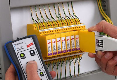
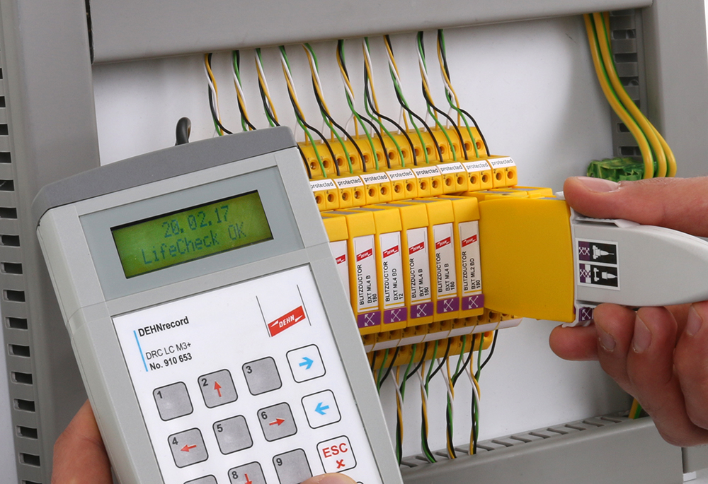
Quick and simple testing of the protection modules in the BLITZDUCTOR XT series is possible using the hand-held test devices DRC LC M1+ and M3+.
To conduct the test the module is simply pulled out of the base part. The snap-on feature of the test sensor facilitates the removal of the arrester module for the test.
The RFIS transponder integrated in the arrester is tested for damage via the RFID testing sensor. Subsequently, the result of the test is displayed on the hand-held testing device. The user can then quickly and easily exchange any arrester modules recommended for replacement in the status indicator.
Optical differentiation of arrester modules:
The LifeCheck symbol printed on the module enclosure allows us to differentiate between the previous and the modified arrester modules. Both modules can be tested using the RFID testing sensors delivered with the hand-held test devices.
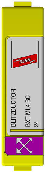 | 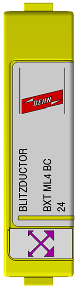 | 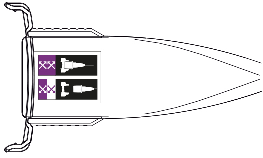 |
| previous | new | additional label on the LifeCheck sensor |
Test procedure
In future, when using the hand-held test devices DRC LC M1+ and DRC LC M3+ to test installations equipped with the new BLITZDUCTOR®s (![]() ) or a mixture (
) or a mixture (![]() ) in the standard LifeCheck mode, the arrester module to be tested must be pulled out of the base part. This ensures that the correct result is obtained. Before testing, the arrester simply needs to be pulled out of the base part by one mechanical module length (approx. 50 mm). The module can then be tested and plugged back into the base part (see pictures).
) in the standard LifeCheck mode, the arrester module to be tested must be pulled out of the base part. This ensures that the correct result is obtained. Before testing, the arrester simply needs to be pulled out of the base part by one mechanical module length (approx. 50 mm). The module can then be tested and plugged back into the base part (see pictures).


1. Clip the test sensor onto the arrester module 2. Pull the arrester module out of the base part
by one mechanical length (approx. 50mm)


3. Start the test and wait for the result


4. Plug the module back into the 5. Remove the test sensor from the arrester module
base part so that it locks in (audibly) and go on to test the next arrester (à step 1)

- Clip the test sensor onto the arrester module
- Pull the arrester module out of the base part by one mechanical length (approx. 50mm)
- Start the test and wait for the result
- Plug the module back into the
- Remove the test sensor from the arrester module and go on to test the next arrester (à step 1)
The user has the following advantages:
- Unambiguous testing of the arrester which is pulled out for pre-damage
- It is immediately recognisable which arrester is being tested (even when the testing procedure is interrupted by the user).
- When using the universal base part BXT BAS as a feed-through terminal, the signal is still available when the arrester module is taken out.
- The operation of the condition monitoring devices DRC MCM XT and DRC SCM XT is not affected and remains as before.