CUI Conductor
Details


IEC/EN 62305-3 points out that in special cases outside of a building the rsik of step and touch voltage may be extremely dangerous, although there is a lightning protection system in accordance with the state of standardisation.
As applies for example, if bare/uninsulated down conductors and lightning protection earth electrodes are installed near the entrance of sheltering areas of buildings with high visitor frequency, such as theatres, cinemas, shopping centres etc.
Especially exposed (lightning endangered) buildings or structures of public access (e.g. shelters) may also require protection measures against step and touch voltage.
Protection against touch voltage
Touch voltage means a life-threatening voltage that affects a person who touches the down conductor while standing on the ground within a distance of about 1 m from the down conductor touches the down conductor. The current flows through the hand into the body and down to the feet (see Figure 1/2).
The hazardous area for persons outside of a building is defined as an area of 3 m around the down conductor and from ground level up to a height of approx. 3 m.
Figure 3 and Figure 4
- Effective protection measures against injuries due to touch voltage are defined according to the standard as follows:
- Installation of an insulated (coated) down conductor providing a surge withstand capability of 100 kV at 1.2/50 µs, e.g. an at least 3 mm thick cross-linked polyethylene.
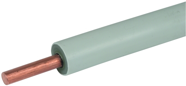
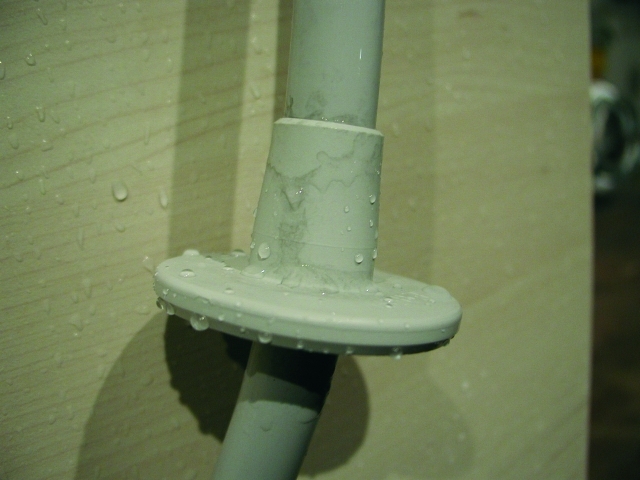
- physical restrictions and /or warning signs to minimise the possibility down conductors being touched. The CUI conductor (CU copper Insulated) has an inner cooper conductor with a diameter of 8 mm and a high-voltage-resistant insulation (see Figure 3).Requirements: – Surge withstand capability of 100 kV (1.2/50 µs)– Prevention of creepage spaarkover even at rainThe surge withstand capability of 100 kV (1.2/50 µs) is achieved by a special cross-linked polyethylene insulation (XLPE). Unless additional measures are taken, high impulse voltages cause sparkovers on insulating surfaces. This effect is known as creeping discharge. If the creeping discharge inception voltage is exceeded, a surface discharge will be initiated, which can easily spark over a distance of several metres to earthed parts. In order to avoid arising creeping discharges even at rain, the CUI conductor additionally has shield which keeps the conductor dry. This shield of the conductor and the drops after the rain test is shown in Figure 4.
Figure 5 and Figure 6
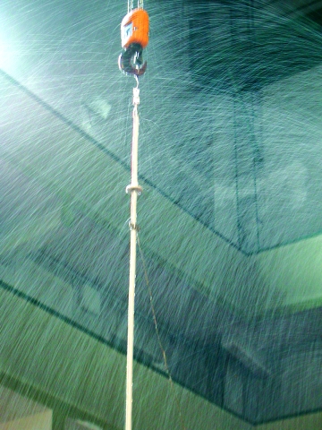
Development of the CUI conductor is based on the ''rain test'' according to IEC 60-1 Subclause 9.
At this test a defined quantity of water is sprayed on the conductor in an angle of approx. 45° (see Figures 4 and 5).
The CUI conductor is available in two standard lengths of 3.5 m and 5 m for vertical installation at the wall with corresponding conductor holders. One head piece and the shield are factory-assembled. The conductor can be shortened on site but can not be extended.
Disconnecting or MV clamps e.g. can be used for connection to the down conductor. Cross units e.g. with additional corrosion protection measures shall be provided to connect the CUI conductor to the earth-termination system.
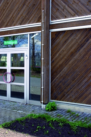
Fig. 6 shows a CUI conductor installed in the entrance area of multipurpose hall.
With the patented CUI conductor system touch voltage at down conductors can be avoided.
At this test a defined quantity of water is sprayed on the conductor in an angle of approx. 45° (see Figures 4 and 5).
The CUI conductor is available in two standard lengths of 3.5 m and 5 m for vertical installation at the wall with corresponding conductor holders. One head piece and the shield are factory-assembled. The conductor can be shortened on site but can not be extended.
Disconnecting or MV clamps e.g. can be used for connection to the down conductor. Cross units e.g. with additional corrosion protection measures shall be provided to connect the CUI conductor to the earth-termination system.
Fig. 6 shows a CUI conductor installed in the entrance area of multipurpose hall.
With the patented CUI conductor system touch voltage at down conductors can be avoided.